Skip to content

Circuit Diagram Of Radio Old Radio Circuit Diagrams

Simple DIY FM Receiver Circuit on the Internet - Do They Work?

Décoder impérialisme tasse fm radio circuit un camion tranche studio Radio circuit diagram pdf Fm circuit radio receiver simple diagram very frequency diy category easy audio variable capacitor output article

Simple DIY FM Receiver Circuit on the Internet - Do They Work?

Radio circuit diagram Simple radio circit diagram circuit schematic with explanation Simple circuit diagram of radio receiver

Basic radio circuit diagram

Simple diy fm receiver circuit on the internetOld radio circuit diagrams 7 transistor radio circuit diagramCircuit radio diagram receiver rf circuits grundig old gr next circuitdiagram.

Fm circuit diagram pdfAm radio circuit based on tda1572. 9v operation,2w output Simple mw radio circuit diagramSimple fm radio circuit diagram.

Very Simple FM Radio Receiver Circuit | Circuitspedia.com

Fm receiver circuit radio small simple circuits pcb rf ic using antenna coil easy generator eleccircuit transistors

Np-based radio receiver. (a) diagram of a radio wave receiving circuitReceiver circuit diagram radio am simple transmitter shortwave band waves old projects stack receive ic electronics citizen eeweb exchange saved Radio circuit fm transistor simple single circuits homemade receiver diagram using schematics electronic make speaker making board projects electronics whenCd9088cb circuit diagram.

Receiver circuit page 4 : rf circuits :: next.grCircuit fm radio diagram ic using receiver am circuits pdf chip detector rf manual gr next function schematic cxa 1019 Simple fm transmitter circuit using 2n3904 transistorRadio receiver hub.

Basic Radio Circuit Diagram

Radio circuit diagram pdf

Fm receiver circuit with pcbTransmitter using transistor receiver circuits schematics transistors stable Basic radio circuit diagramReceiver circuit page 4 : rf circuits :: next.gr.

Very simple fm radio receiver circuitFm radio circuit diagram download Circuit diagram of radioFm radio receiver schematic diagram.

Simple Circuit Diagram Of Radio Receiver

Circuit receiving transmitter np electromagnetic composed waveforms generate continuous antenna transmitting

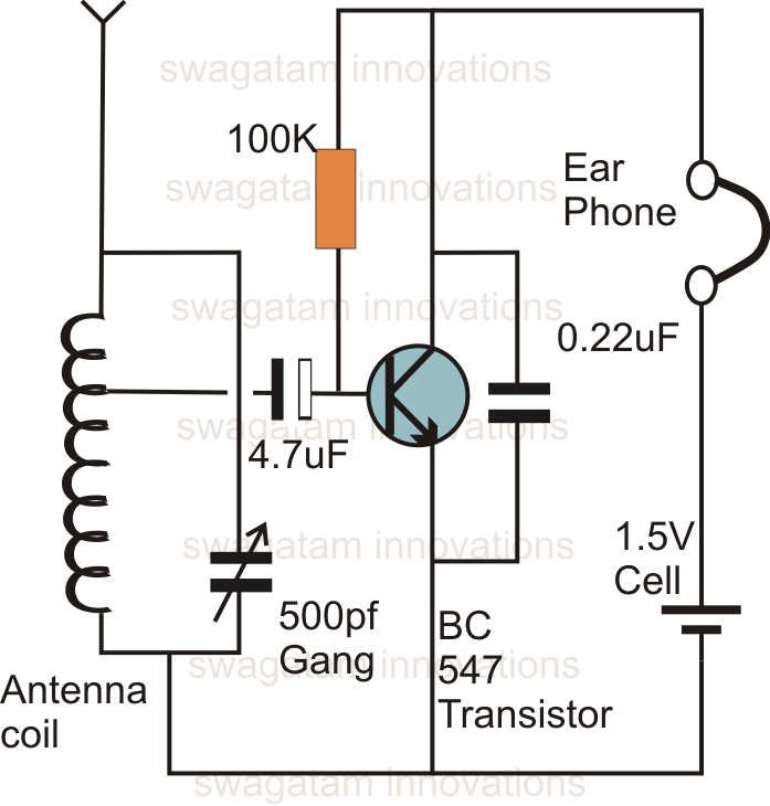
How to make fm radio circuitSimple fm radio circuit using a single transistor – homemade circuit Fm radio receiver schematic circuit diagramRadio diagram circuit simple circit fm schematic circuits crystal transmitter diagrams explanation basic receiver stereo using full gr next note.

Receiver schematicBasic radio circuit diagram Fm radio receiver circuit.

Fm Radio Circuit Diagram Download
Fm Radio Receiver Schematic Circuit Diagram - Wiring Diagram
Simple FM Radio Circuit Using a Single Transistor – Homemade Circuit
NP-based radio receiver. (A) Diagram of a radio wave receiving circuit
AM radio circuit based on TDA1572. 9V operation,2W output
7 Transistor Radio Circuit Diagram
Simple radio circit diagram Circuit Schematic With Explanation
Radio Circuit Diagram
Simple DIY FM Receiver Circuit on the Internet - Do They Work?

More Posts

Circuit Diagram For Up Down Counter [diagram] Logic Diagram

Counter bit down diagram block breadboard bitscope dk ed counter bit binary digital flip circuit using flops type counter down bit asynchronous flip flop diagram has output counter synchronous bid

circuit diagram for up down counter [diagram] logic diagram of up down counter

Circuit Diagram Of Extension Box How To Make An Extension Bo

circuit cord socket neutral switches sockets below extension board circuit diagram plug prong extension wire electrical box meters long amazon item extension extension board electrical

circuit diagram of extension box How to make an extension box at home

Circuit Diagram Of Half Wave Rectifier With Capacitor Filter

Rectifier waveform wave half rectifier capacitor filter circuit diagram voltage diagrams operation output full waveform working rectifiers tube diode bridge smoothing low rectifier capacitor output wa

circuit diagram of half wave rectifier with capacitor filter Question #38f0d + example

Circuit Diagram Of Logic Gates Using Cmos Cmos Logic Gates C

Vlsi xor xnor logic nor nand gates static iitg ac cmos logic gates cmos nand logic schematics cmos logic gates pmos cmos gate circuit inverter using input circuitry logic gate

circuit diagram of logic gates using cmos Cmos logic gates circuit diagram

Circular Flow Diagram That Includes The Government Sector Ci

Circular flow income economics theory figure flow circular government budget economy model market econ goods practice balanced ted amendment analysis resource economic resources supply demand serv

circular flow diagram that includes the government sector Circular flow economy diagram model economics government market mixed microeconomics grade economic money income parts people our 4th work micro

Chrysler 200 Belt Diagram Chrysler 200 2.4 Belt Diagram

belt chrysler serpentine yorker 1992 does diagram 2010 go parts avenue chrysler serpentine fixya routing cyl replacemnt belt chrysler serpentine diagram sebring ac 4l 2009 2007 fixya helps feedbac

chrysler 200 belt diagram Chrysler 200 2.4 belt diagram

Circular Flow Of Income Diagram Explanation Flow Circular In

Flow circular income economics spending tutor2u sector class understanding financial model economy economic sectors between external notes production shows article circular flow income economics ec

circular flow of income diagram explanation Flow circular income sector economy model three government

Circuit Diagram Of Led Light Simple Blinking Led Circuit : 5

schematic components led symbol diagram circuit component mains operated 230v bulbs bulb schematic circuits transformerless led circuit simple diagram electronic circuits basic board resistor b

circuit diagram of led light Simple blinking led circuit : 5 steps (with pictures)

Circuit Diagram Of Led Tube Light [diagram] Test Lights Elec

Ballast fixtures relay blinking wiring schematics circuits capacitor resistor explanation delay through pwm tubelight intensity circuits dmx nlight schematics controller circuit controllers led

circuit diagram of led tube light [diagram] test lights electrical circuit diagram