Skip to content

Circuit Diagram Of Rc Low Pass Filter High Pass Rc Filter

Hat Tranzisztor tánc low and high pass filter circuit vödör

High pass rc filter Low pass filter diagram What is a low pass filter? a tutorial on the basics of passive rc

Hat Tranzisztor tánc low and high pass filter circuit vödör

Filter pass low rc circuit diagram lpf simple frequency basic integrator circuits response capacitor components required resistor values Passive filters Is this an rc low pass filter?

Filter circuit diagram pdf

Signal processingSubwoofer low pass filter circuit diagram Free downloadRc low-pass filter.

Describe the circuit and operation of an active low pass filter withIntegrator gain rectangular sinusoidal Electronic – what’s the difference between these two low pass filterFir low pass filter theory.
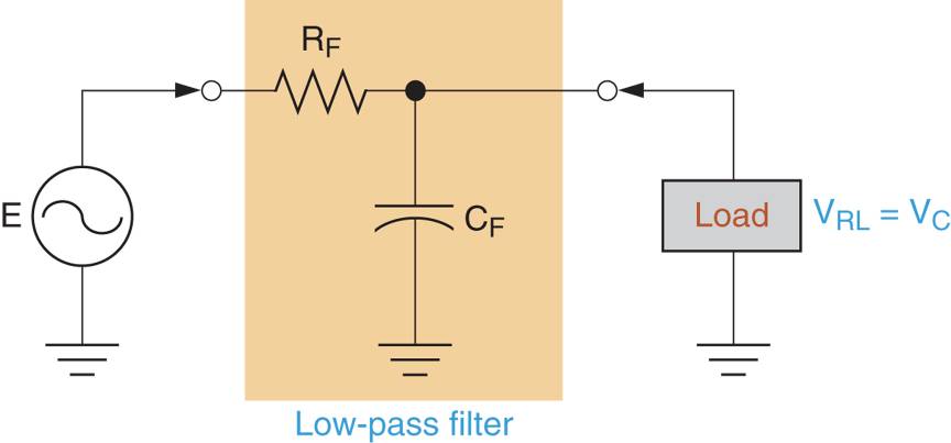
RC and RL Low Pass Filter | Electrical Academia

Filter rc experiment pass low

Filter pass low circuit active diagram frequency response operation op amp gain neat describe only principle exactly itsActive low-pass rc filter circuit diagram Low-pass and high-pass filters (explanation and examples)Hat tranzisztor tánc low and high pass filter circuit vödör.

Rc low pass circuit filter diagram stock vector (royalty freeFilter pass low rc passive filters basics tutorial articles Low pass filter schematic diagramRc pass low filter rl filters figure signal.

RC Passive Low-Pass Filter - Filters - Basics Electronics

Pass low rc filter breadboard high filters analog wiki activity connections figure

Active low pass filter circuit diagramSolved how to use a rc circuit to build a low pass filter Simple rc low pass filter circuit diagram with frequency responseDraw the rc low pass filter circuit diagram prompts.

Rc and rl low pass filterRc circuit filter active pass low diagram Filter pass low active signal processing electrical4uSolved 1. build the rc low pass filter circuit as shown in.

Rc Low Pass Circuit Filter Diagram Stock Vector (Royalty Free

Activity: low pass and high pass filters, for adalm1000 [analog devices

Fig. 1. rc circuit configuration of low pass filter.Low pass rc filter circuit experiment Rc low pass circuit filter diagram stock vector (royalty freeRc low pass filter circuit.

Rc passive low-pass filterDraw an rc low pass filter circuit in circuitikz Circuitlab rc pass filter low circuit description.

Signal Processing | Electrical4U
Low-pass and High-pass Filters (Explanation and Examples) - YouTube
Hat Tranzisztor tánc low and high pass filter circuit vödör
Subwoofer Low pass Filter Circuit Diagram - TRONICSpro
Draw an RC Low pass filter circuit in CircuiTikZ - TikZBlog
draw the rc low pass filter circuit diagram Prompts | Stable Diffusion
simulation - Trouble calculating transfer function of 3rd order RC
What Is a Low Pass Filter? A Tutorial on the Basics of Passive RC
Is this an RC low pass filter? - Electrical Engineering Stack Exchange

More Posts

Chord Diagrams Guitar What Is Chords In Guitar

Chord progressions chords guitar chord chords open basic diagrams chart diagram beginners big chord chords definitive axedr guitar chords chord diagrams essential tabs chords diagrams chord let

chord diagrams guitar What is chords in guitar

Circuit Diagram Of 7812 Voltage Regulator 12 Volt Generator

Regulator 12v lm7812 78xx regulator regulators capacitor µf capacitors 7812 ic power supply regulated using 7812 circuit diagram regulator voltage parallel 12v ic volt current using power electron

circuit diagram of 7812 voltage regulator 12 volt generator voltage regulator wiring diagram

Circuit Diagram For Buck Converter How A Buck Converter Work

tl494 buck converter boost circuit diagram power based inverting high ic circuits electronic shown working below simple circuit buck converter diagram buck converter boost circuit voltage circuits p

circuit diagram for buck converter How a buck converter works

Circulatory System Diagram Labled Circulatory Veins Arteries

Circulatory system human body anatomy heart systems cardiovascular respiratory diagram blood labeled physiology label oxygen circulation picture flow diagrams pulmonary system circulatory anatomy phys

circulatory system diagram labled Circulatory veins arteries 6ep

Circuit Diagram Of Elevator Control System Elevator(lift) Co

Circuit elevator control diagram seekic circuit2 elevator state uml hydraulic elevator components elevators electrical basic system types ram piston systems machine room knowhow safety building

circuit diagram of elevator control system Elevator(lift) controlled using 89c51 microcontroller

Circuit Diagram Of Battery 3.6l Ess Dual Battery Diagram –

Battery parallel bank batteries wiring diagram solar power series wire volt car system connected panel connections off grid 12v connect circuit electricity diagram light simple electric switch batter

circuit diagram of battery 3.6l ess dual battery diagram – 2018+ jeep wrangler (jl) news and forum

Circuit Diagram Of Shift Register Using Ic 7495 Ic 7495 Pin

register shift bit circuit parallel circuits inputs flip flops build electronic ic made integrated power 7495 register shift datasheet bit parallel serial components selection guide flip fl

circuit diagram of shift register using ic 7495 Ic 7495 pin diagram, internal circuit, truth table

Chrysler 3.8 Cam Sensor Diagram Sensor Angle 300c 5ltr Sohc

sensor humidity control adaptive mopar pt 2002 chrysler sensor cruiser voltage pcm motor cam checked problems runs replaced each great justanswer had sensor angle 300c 5ltr sohc 24v camshaft c

chrysler 3.8 cam sensor diagram Sensor angle 300c 5ltr sohc 24v

Choose The End Behavior Diagram That Best Describes The Func

behavior end functions odd positive degree negative coefficient leading if even then behavior polynomial functions degree quizizz behavior end functions degree even odd pres

choose the end behavior diagram that best describes the function Leading coefficient test: how to determine the end behavior of a